Rendering a cube
We already have all the pieces needed to render a 3D scene but we need first to do the maths.
Projection matrix
We need first to define what do we want to view, that is, we need to define a viewing volume such that any object within the volume (even partially) will be rendered while objects outside won’t. On the image below, the yellow and red spheres are within the volume while the green one is not and does not appear on the projection.
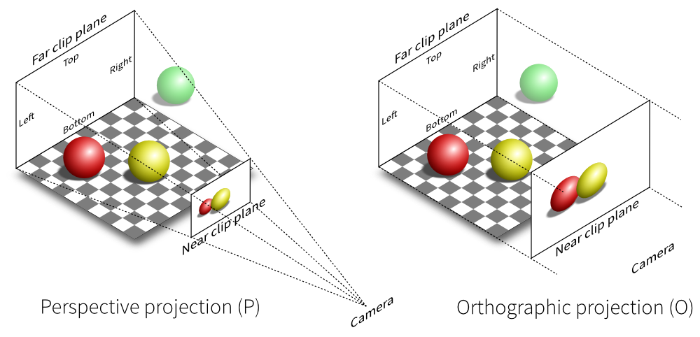
There exist many different ways to project a 3D volume onto a 2D screen but we’ll only use the perspective projection (distant objects appear smaller) and the orthographic projection which is a parallel projection (distant objects have the same size as closer ones) as illustrated on the image above. Until now (previous section), we have been using implicitly an orthographic projection in the z=0 plane.
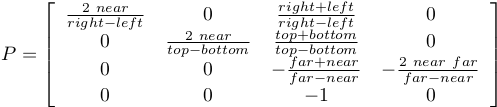
Depending on the projection we want, we will use one of the two projection matrices below:
Perspective matrix
Orthographic matrix
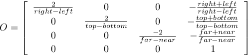
At this point, it is not necessary to understand how these matrices were built. Suffice it to say they are standard matrices in the 3D world. Both suppose the viewer (=camera) is located at position (0,0,0) and is looking in the direction (0,0,1).
There exists a second form of the perpective matrix that might be easier to manipulate. Instead of specifying the right/left/top/bottom planes, we’ll use field of view in the horizontal and vertical direction:
Perspective matrix
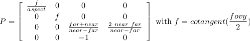
where fovy specifies the field of view angle, in degrees, in the y
direction and aspect specifies the aspect ratio that determines the field
of view in the x direction.
Model and view matrices
We are almost done with matrices. You may have guessed that the above matrix requires the viewing volume to be in the z direction. We could design our 3D scene such that all objects are withing this direction but it would not be very convenient. So instead, we’ll use a view matrix that will map the the world space to camera space. This is pretty much as if we were orienting the camera at a given position and look toward a given direction. In the meantime, we can further refine the whole pipeline by providing a model matrix that will maps the object’s local coordinate space into world space. For example, this wil be useful for rotating an object around its center. To sum up, we need:
- Model matrix maps from an object’s local coordinate space into world space
- View matrix maps from world space to camera space
- Projection matrix maps from camera to screen space
Now, we can write out shaders:
vertex = """
uniform mat4   u_model;         // Model matrix
uniform mat4   u_view;          // View matrix
uniform mat4   u_projection;    // Projection matrix
attribute vec3 a_position;      // Vertex position
void main()
{
    gl_Position = u_projection * u_view * u_model * vec4(a_position,1.0);
} """

fragment = """
void main()
{
    gl_FragColor = vec4(1.0, 0.0, 0.0, 1.0);
} """
Building a cube
We need to define what we mean by a cube since there is not such thing as as cube in OpenGL. A cube, when seen from the outside has 6 faces, each being a square. We just saw that to render a square, we need two triangles. So, 6 faces, each of them being made of 2 triangles, we need 12 triangles.
How many vertices? 12 triangles × 3 vertices per triangles = 36 vertices might be a reasonable answer. However, we can also notice that each vertex is part of 3 different faces actually. Instead we’ll use no more than 8 vertices and tell explicitly OpenGL what to draw with them:
V = np.zeros(8, [("a_position", np.float32, 3)])
V["a_position"] = [[ 1, 1, 1], [-1, 1, 1], [-1,-1, 1], [ 1,-1, 1],
                   [ 1,-1,-1], [ 1, 1,-1], [-1, 1,-1], [-1,-1,-1]]
These describe vertices of a cube cented on (0,0,0) that goes from (-1,-1,-1)
to (+1,+1,+1). Then we compute (mentally) what are the triangles for each face, i.e. we
describe triangles in terms of vertices index (relatively to the V array we
just defined):
I = np.array([0,1,2, 0,2,3,  0,3,4, 0,4,5,  0,5,6, 0,6,1,
              1,6,7, 1,7,2,  7,4,3, 7,3,2,  4,7,6, 4,6,5], dtype=np.uint32)
We now need to upload these data to the GPU. Using gloo, the easiest way is to use a VertexBuffer for vertices data and an IndexBuffer for indices data:
V = V.view(gloo.VertexBuffer)
I = I.view(gloo.IndexBuffer)

cube = gloo.Program(vertex, fragment)
cube["a_position"] = V
We’ll use the indices buffer when rendering the cube.
Building matrices
Note
Note that the view matrix is a translation along z. We actually move away from the center while looking into the (positive) z direction.
All the common matrix operations can be found in the glumpy.glm module
that defines ortho, frustum and perspective matrices as well as rotation,
translation and scaling operations. We won’t say much more about these and you
might want to read a book about geometry to understand how this work,
especially when compositing rotation, translation and scaling (order is
important):
view = np.eye(4,dtype=np.float32)
model = np.eye(4,dtype=np.float32)
projection = np.eye(4,dtype=np.float32)
glm.translate(view, 0,0,-5)
cube['u_model'] = model
cube['u_view'] = view
cube['u_projection'] = projection
phi, theta = 0,0
It is now important to update the projection matrix whenever the window is resized (because aspect ratio may have changed):
@window.event
def on_resize(width, height):
   ratio = width / float(height)
   cube['u_projection'] = glm.perspective(45.0, ratio, 2.0, 100.0)
Rendering
Rotating the cube means computing a model matrix such that the cube rotate around its center. We’ll do that in the draw function and rotate the cube around the z axis (theta), then around the y axis (phi):
@window.event
def on_draw(dt):
    global phi, theta
    window.clear()
    cube.draw(gl.GL_TRIANGLES, I)

    # Make cube rotate
    theta += 0.5 # degrees
    phi += 0.5 # degrees
    model = np.eye(4, dtype=np.float32)
    glm.rotate(model, theta, 0, 0, 1)
    glm.rotate(model, phi, 0, 1, 0)
    cube['u_model'] = model
We’re now alsmost ready to render the whole scene but we need first to modify the initialization a little bit to enable depth testing:
@window.event
def on_init():
    gl.glEnable(gl.GL_DEPTH_TEST)
This is needed because we’re now dealing with 3D, meaning some rendered triangles may be behind some others. OpenGL will take care of that provided we declared our context with a depth buffer which is the default in glumpy.
Complete source code is available on github.
But… But… But is’t ugly ! Yes, of course ! We have no color (but red), no texture and no light. What did you expect ?